Reaching the Standard: Analyzing the Dynamic Behavior of Crane Drives Using SimulationX
- jlodewyk
- Sep 6, 2024
- 3 min read
Summary of Presentation from the 2012 ESI SimulationX User Forum
Conference Paper by Uwe Schreiber, Paul Rodionow, ESI ITI GmbH
The dynamic behavior of crane drives under various loads and operational scenarios is difficult to analyze using static finite element (FE) analysis. Because of its faster computation time, SimulationX was used to model the dynamic performance of a double-jib, level luffing crane and a Liebherr lattice boom crane, calculating the load lifting and dropping coefficients of the level luffing crane to be 1.44 and 0.3936 respectively.
Figure 1: Schematic of a double jib level luffing crane
Level Luffing Crane Model
The double jib level luffing crane model consists of multiple subsystems: MBS mechanics, rope hoisting, drive, and grab. The MBS mechanics subsystem includes rigid bodies and their masses, which are imported from the crane's CAD model and assembled into two four-bar linkages. The rope hoisting subsystem features three pulleys, a preset element functioning as the hoist, and elastic belts that simulate the lifting cable by transmitting only drag forces. The drive subsystem is defined using 1D rotational mechanics elements and incorporates a drive control system to adjust motor torque. Finally, the grab subsystem models the weight of the crane grab, the variable load it carries, and its interaction with the ground.

Figure 2: Diagram view of the model
Load Scenario Analysis
The load scenario used to analyze the loading coefficients of the luffing crane involves several steps: initially lifting and lowering an empty grab off the ground, filling the grab, repeating the lifting and lowering maneuver, and ultimately releasing the entire load.
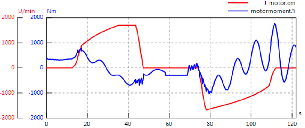
The maximum motor torque applied to extend the rack and adjust the jib's position is 750 Nm when luffing out unloaded and 1,750 Nm when luffing in fully loaded. The rope force required to lift the fully loaded grab fluctuates significantly, reaching a maximum of 704.6 kN, which is more than double the force needed to lift the grab when it is empty.

Figure 3: Graph of Motor speed and torque

Figure 4: Rope force, lifting speed and load mass
Using the maximum lifting force and a load mass of 50 tonnes, the load lifting coefficient is calculated to be 1.44. The minimum force in the cable when dropping the load is 196 kN with a maximum cable force of 498 kN before the drop, producing a coefficient of 0.3936. These coefficient results satisfy the requirements of DIN EN 13001-2.
Lattice Boom Crane Model
A separate SimulationX model was developed for the Liebherr lattice boom crane LR 1600 to calculate the cable forces and winch torques required to raise the crane. Simulation results indicated that the cables actuating the jib are subject to the highest cable force. Both cable forces and winch motor torques displayed significant overshoot, highlighting the need for further design optimization and controller development of the crane.
Figure 9: Rope forces of winches W1 (beltSpring1), W3 (beltSpring7) and W5 (beltSpring7)
Figure 10: Motor torques for winches W1, W3 and W5
References
[1] Manual SimulationX 3.5. Dresden: ITI GmbH, 2011.
[2] DIN EN 13000 „Cranes –Mobile cranes“
[3] DIN EN 13001-1 „Cranes – General design – Part 1: General principles and requirements“. Abschnitt 4.2 „Rechnerischer Nachweis“.
[4] DIN EN 13001-2 „Crane safety – General design – Part 2: Load actions“. Abschnitt 4.2.2 „Regelmäßige Lasten“.
If interested in additional information, please contact us for the full proceedings of the 2012 ESI SimulationX User Forum.


Comments